Digital Design Lab - Java Bread Board Simulator
Objective: To study, design and implement a binary to gray and gray to binary converter using basic gates.
Apparatus required: Breadboard, power supply, X-or gate IC 7486, connecting wire.
THEORY:
The reflected binary code, also known as Gray code after Frank Gray, is a binary numerical system where two successive values differ in only one bit. The reflected binary code was originally designed to present spurious output from electromechanical switches. Today Gray codes are widely used to Facilitate error correction and digital communications such as digital terrestrial television and some cable TV systems.
FORMING GRAY CODE:
The binary reflected gray code list for n bits can be generator recursively from the list for n-1 bits by reflecting the list (i... e, listing the entries in reverse order). Concatenating the original list with the reversed list, prefixing the entries in the original list with a binary 0, and then prefixing the entries in the reflected list with a binary 1. For example, generating the n=3 list from the n = 2: given below:
BINARY TO GRAY CODE CONVERSATION:
The logical circuit which converts binary code to equivalent Grey code is know as binary to grey code converter. The Grey code is a non weighted code. The successive Grey code differs in one bit position only, that means it is a unit distant code. It is also referred as a cyclic code. It is not suitable for Arithmetic operations. It is the most popular of the unit distance code. It is also reflective code. An n-bit grey code can be obtained by reflecting an n – 1 bit code. About an axis after 2^n- 1 rows, and putting the MSB of 0 above the axis and there MSD of 1 below the axis. Reflection of gray codes is shown below in the conversion table.

Fig 1: Conversion table from Binary to Gray Converter.

Fig 2: Circuit Diagram for Binary to Gray Code Converter
GREY TO BINARY CODE CONVERTER
In gray to binary code converter, input is a multiplied grey code and output is its equivalent binary code. Let us consider a 4-bit grey to binary code converter. To design a 4-bit grey to binary code converter, we first have to draw a conversion table.
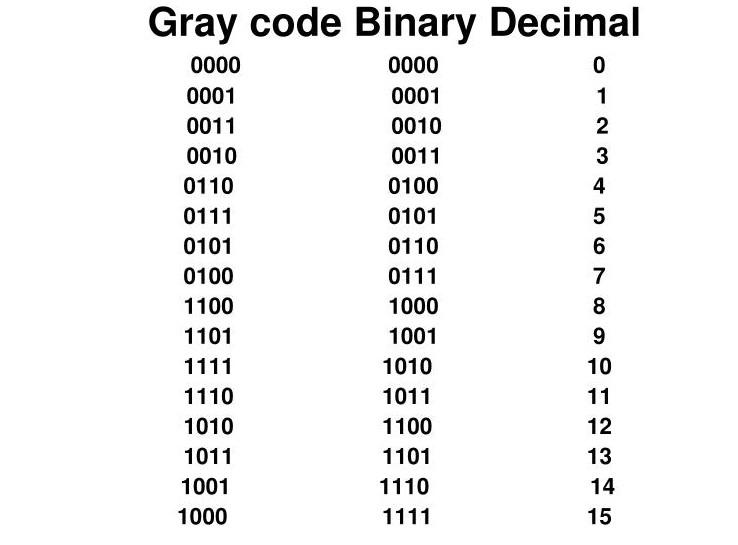
Fig 3: Conversion table for Gray to Binary code.
CIRCUIT DIAGRAM OF GRAY TO BINARY CODE CONVERTER
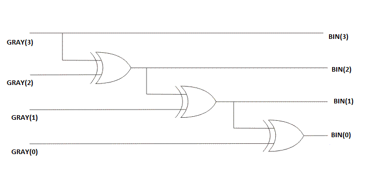
Fig 4: Logic circuit diagram of Gray to Binary code converter
PROCEDURE:
Construct the circuit for binary to grey code converter.
Give inputs to it and match corresponding outputs.
Now construct the circuit for grey to binary code converter.
Give inputs to it and match corresponding outputs.
RESULT:
The inputs and outputs are matched for both binary to gray and gray to binary code converter circuits.
PRECAUTIONS:
All the ICs should be checked before using the Apparatus.
All connections should be tight.
Always connect ground first and then VCC.
The circuit should be off before changing the conversations.
After completing the experiment, switch off the supply to apparatus.


0 Comments