Digital Design Lab - Java Bread Board Simulator
Objective: - To design and study multiplexers and demultiplexers using IC’s.
Apparatus Required: - Digital trainer kit, power supply, connecting wires.
IC’s 74LS04 Hex 1-input NOT gate
74LS08 Quad 2-input AND gate
74LS11 Triple 3-input AND gate
74LS32 Quad 2-input OR gate
Theory: -
Multiplexer:
Multiplexer is a logic circuit that has much input but single output. A Multiplexer accepts several data inputs but allows only one at a time to get through to the output. Inputs and outputs are indicated by means of broad allow to indicate that there may be one or more inputs depending upon the digital code applied at the select input. One of the N data sources (D0, D1, ______Dn-1) is selected and translated the single output channel. A 1-to-4-line multiplexer has 4 inputs but only single output.
CIRCUIT DIAGRAM:

To perform a 4 to 1 line multiplexer experiment. We have used IC 74153. It has 4 line inputs Y0 Y1 Y2 Y3 and only one output. Go is the strobe input S0 and S1 are select input lines. Select one out of four inputs at the output for example S0, S1=00 then Y0 will be selected.
TRUTH TABLE:
DEMULTIPLEXER:
It is a combinational circuit that distributes the single input data to a specific output line. The control inputs or selection lines are used to select a specific output line from the possible output lines. It has one data input(D), 2n possible outputs (Y0, Y1, Y2, ……Y2n-1), n selection lines (S0, S1…...Sn). It also has an enable input. The demux will work only when the enable is set to logic 1.
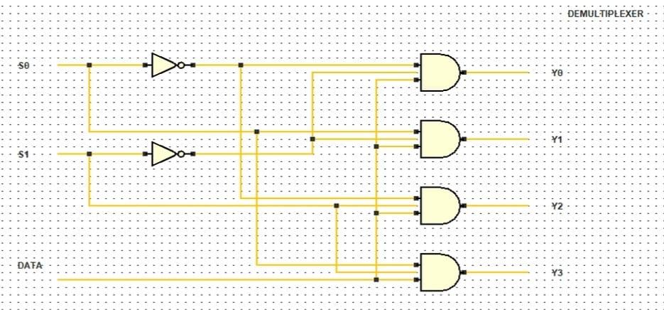
CIRCUIT DIAGRAM:

RESULT:
A 4:1 MUX and 1:4 DEMUX were constructed and their truth tables were verified.
Below is the YouTube Channel link where you will find the experiment performed in the Java breadboard simulator.


0 Comments